Controlling Motor With Raspberry Pi And Python
In this lesson, we’re going see how we can control a DC motor using a Raspberry Pi and Python.
What is a Raspberry Pi?
“The Raspberry Pi is a low cost, credit-card sized computer that plugs into a computer monitor or TV, and uses a standard keyboard and mouse. It is a capable little device that enables people of all ages to explore computing, and to learn how to program in languages like Scratch and Python.” –Raspberry Pi Foundation
In short, a Raspberry Pi is a tiny computer that allows us to connect external hardware and integrate them using software.
Getting Started
Items Needed
For this project, I will be using the following items:
- Raspberry Pi Model B running Raspbian
- L298N Motor Drive Board
- Bread Board
- 5V DC Motor
- 12V Power Supply
- Jumper Cables
While you do not need exactly what I have, I recommend getting the L298N chip already on a PCB as it saves time and spares us from having to wire up the circuit ourselves.
Wiring
Before we can get to programing the motor, we must first wire up the device. We Can begin with the L298N Board.
For the L298N chip, we are only concerned about 6 pins for now. Those six include:
- GND
- In 3
- In 4
- 12V
+-
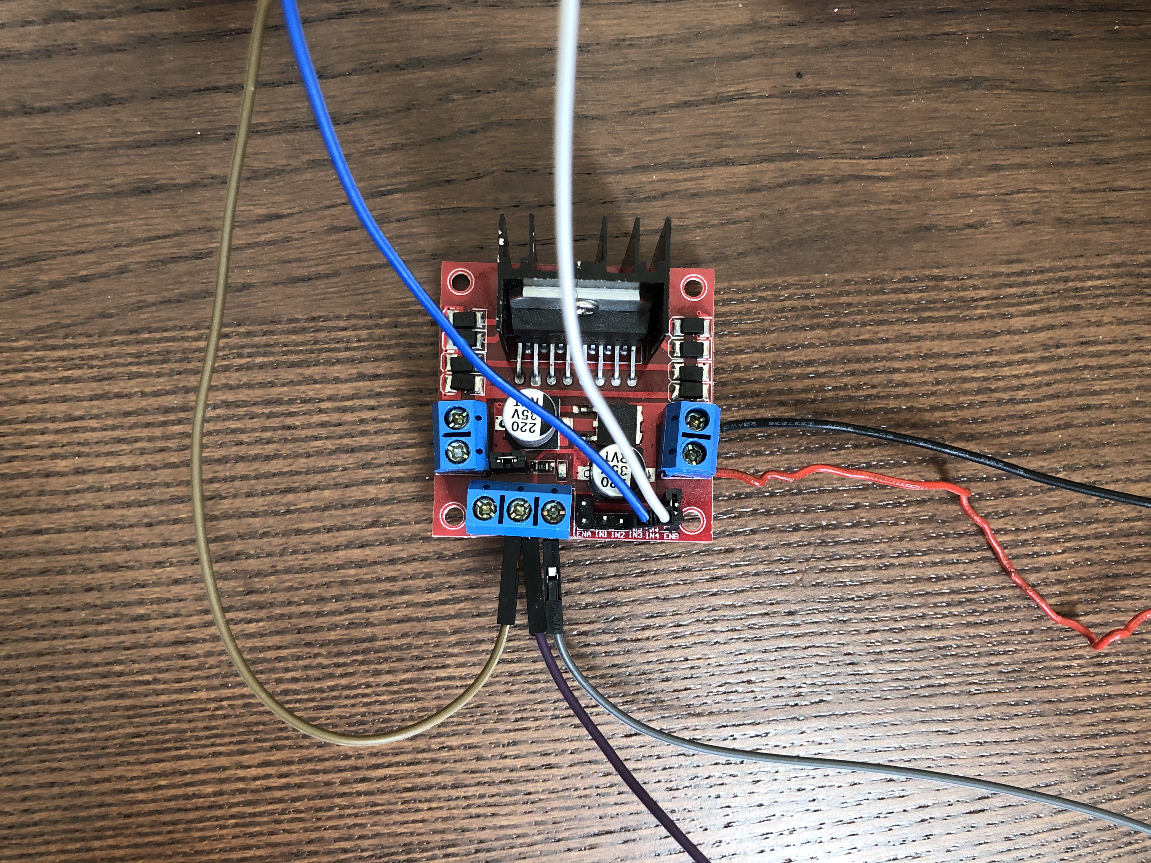
In this picture, the Brown wire and the Purple wire are both connected to GND, the Grey wire is connected to the 12V pin, the Red and Black wires are connected to + and - respectively, and the Blue and White wires are connected to pins In 3 and In 4.
On the Bread Board, we can connect the positive and negative ends of the power supply into their respective lines on the breadboard along with the leads from the pins of the L298N chip.
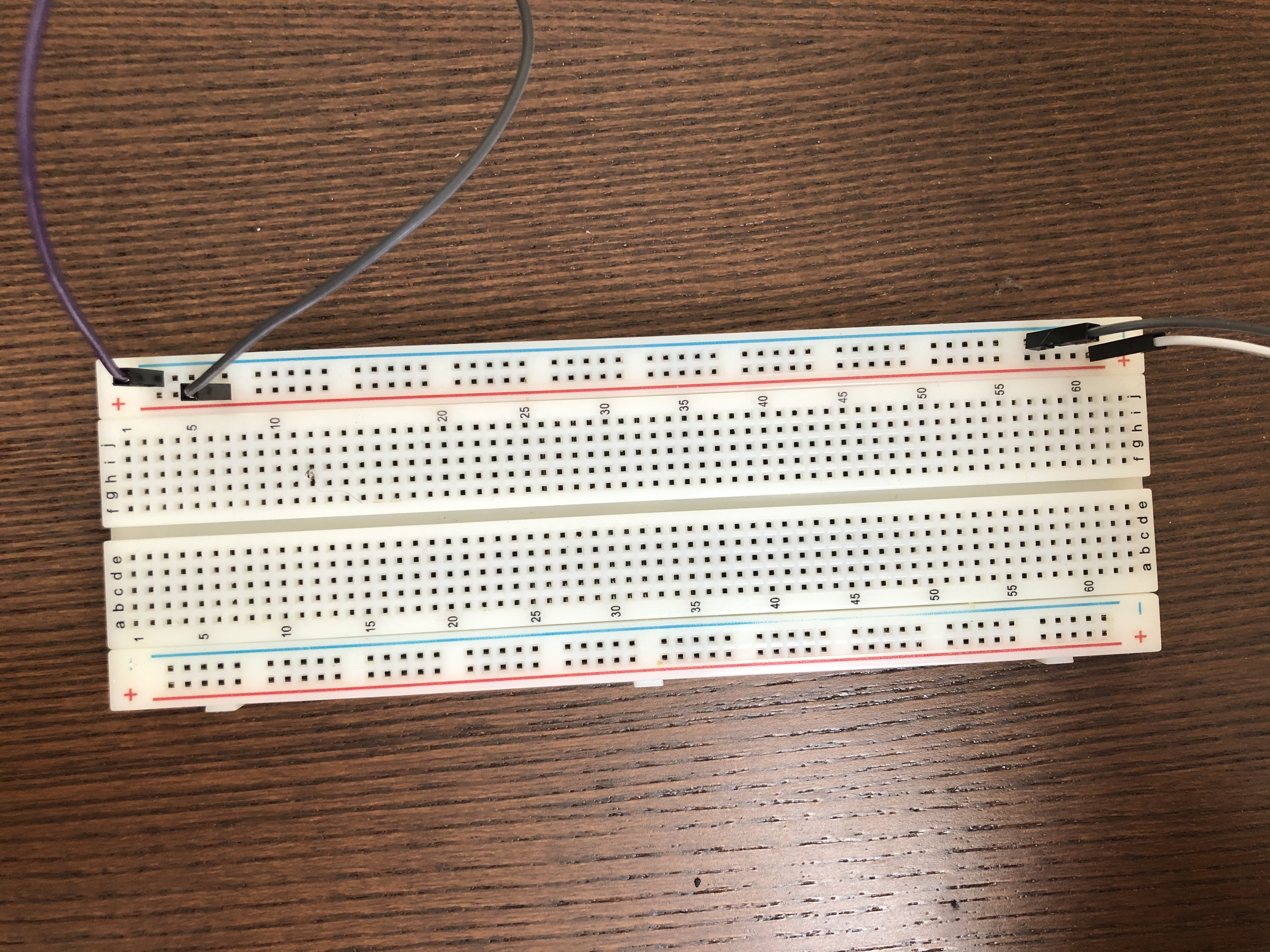
On the far right, the Grey(Positive) and White(Negative) wires are coming from the power supply and the far purple(Negative) and Grey(Positive) are coming from the L298N Chip.
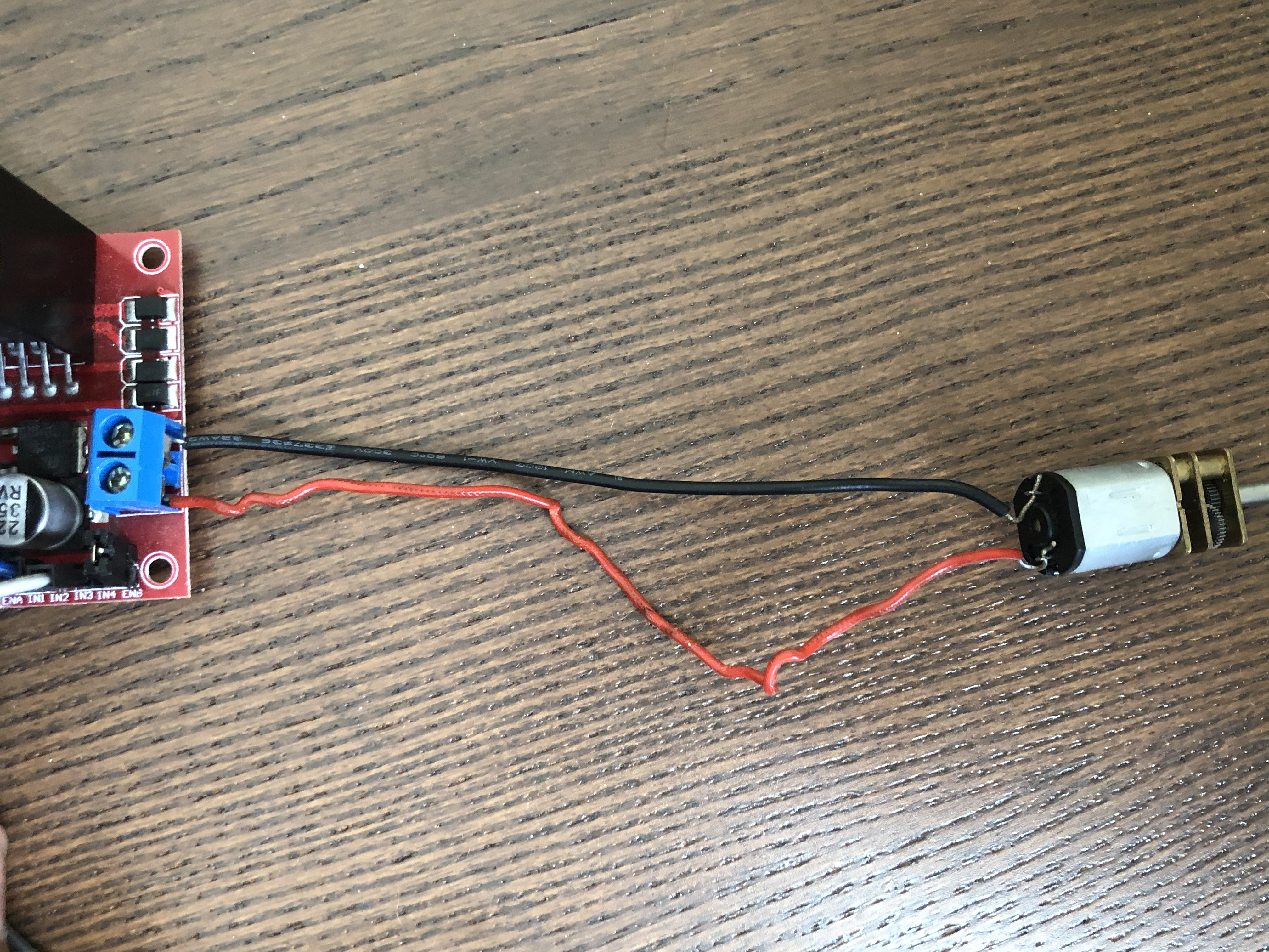
Now we can wire up the motor to the board. Connect the Red(Positive) and Black(Negative) wires from the L298N to the motor leads.
Finally, we can wire up the Raspberry Pi to the rest of the circuit. Before we do so, lets look at the pin structure on the Pi.
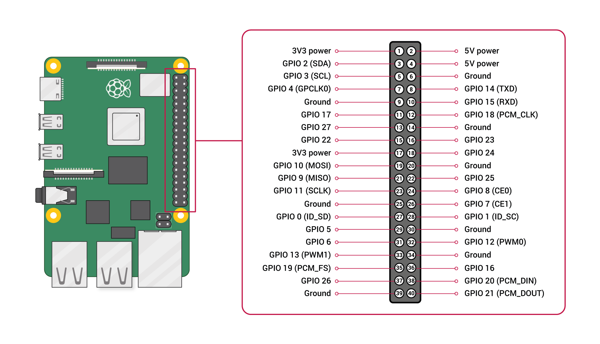
The pins of the Raspberry Pi are numbered from 1 to 40 starting at the top left and increasing by 1 going to the right. Together, these pins are known as GPIO pins (General Purpose Input/Output Pins).
Each pin has a different purpose, but we’re going to only use pins 7, 11, and 39.
Pins 7 and 11 are going to be used to output a signal to the L298N Chip, and Pin 39 is a grounding pin, which will be connected to the same ground as the L298N Chip.
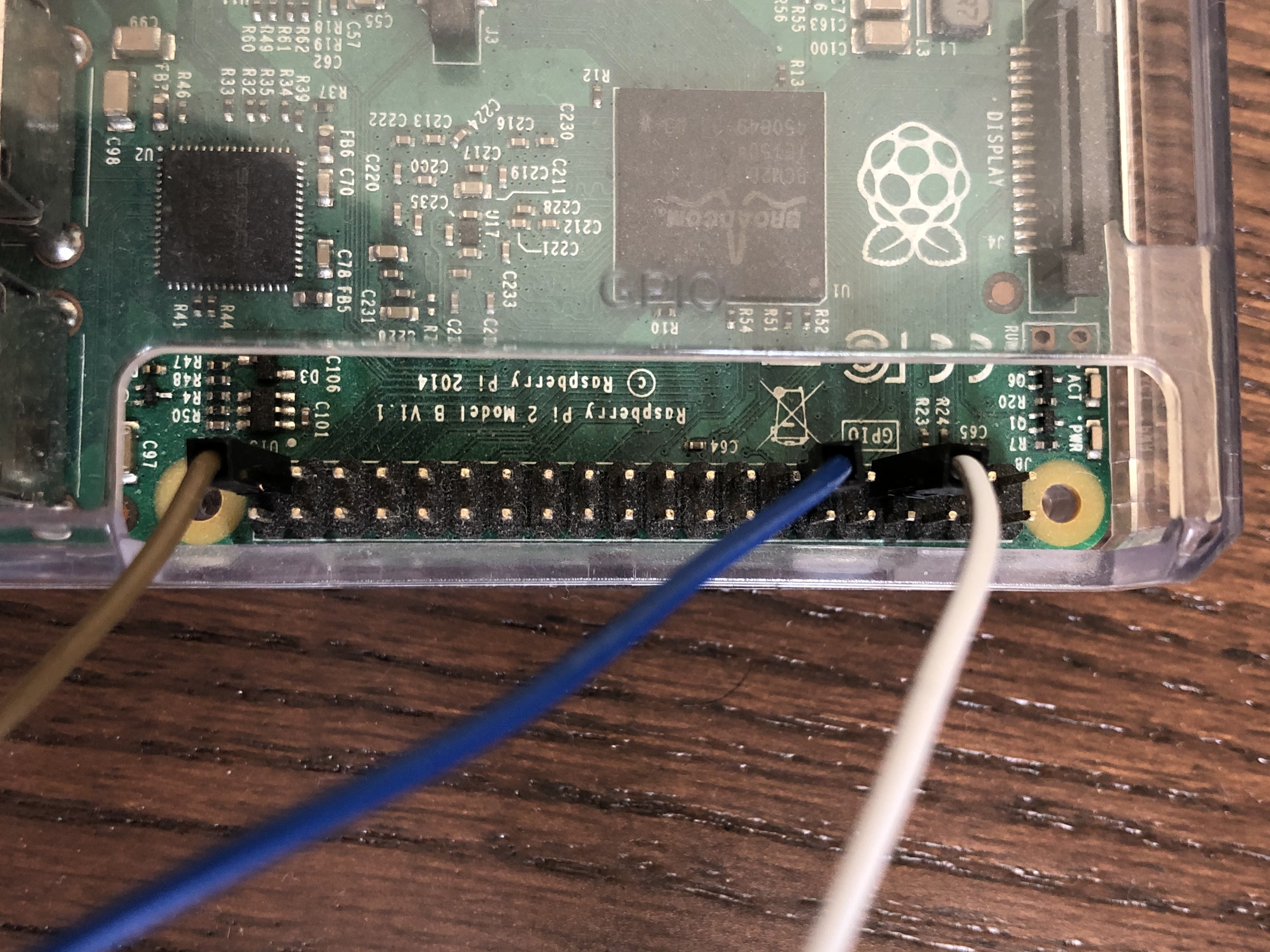
In the image above, the White wire is connected to Pin 7, the Blue wire is connected to Pin 11, and the Brown wire is connected to Pin 39.
Now that we are done with the wiring, we can start coding!
Programming the Raspberry Pi
To program our motor, we are going to use Python. If you are unfamiliar with the Python Programming language, feel free to visit my tutorial found here.
Our friend in this part will the the RPi.GPIO module.
Disclaimer : The Raspberry Pi foundation recommends using bespoke modules for specific hardware. Since we are trying to learn how to use GPIO pins to interface with any external sensors and motors, we will use the old way of interfacing with them.
We can consider using Object Oriented design when implementing our motors. In other words, our motor will be represented by a class.
In a file called motor.py, we will have the following code:
import RPi.GPIO as GPIO # Allows us to interface with the GPIO pins

class Motor:
    # sets 2GPIO pins for clockwise and counter clockwise
    def __init__(self, F, B):
        self.pinFwd = F
        self.pinBwd = B

        GPIO.setmode(GPIO.BOARD) # Sets the pins to use the Board Numbering

        GPIO.setup(self.pinFwd, GPIO.OUT) # Sets pin 1
        GPIO.setup(self.pinBwd, GPIO.OUT) # Sets pin 2

    def __del__(self):
        # Destructor cleans up any open pins
        GPIO.cleanup()

    def forward(self):
        # Sets pin 1 to ON and pin 2 to OFF

        GPIO.output(self.pinFwd, GPIO.HIGH)
        GPIO.output(self.pinBwd, GPIO.LOW)

    def backward(self):
        # Sets pin 1 to OFF and pin 2 to ON

        GPIO.output(self.pinFwd, GPIO.LOW)
        GPIO.output(self.Bwd, GPIO.HIGH)

    def stop(self):
        # Sets both pins to OFF

        GPIO.output(self.pinFwd, GPIO.LOW)
        GPIO.output(self.pinBwd, GPIO.LOW)
In the above code, a motor is defined by 2 main characteristics: a pin forward and a pin backward. The __init()__ method sets the two values for those pins, and methods forward(), backward(), and stop() cause the motor to spin clockwise, counterclockwise, and stop. The __del()__ method is called when the motor object leaves scope, which will close any open pin connections.
Now in another file, call it main.py, we can import the motor class and create object from it.
The main.py file:
import motor # imports our motor.py class
import time

# Instantiates a motor using pins 7, 11
motor1 = motor.motor(7, 11)

motor1.forward()

time.sleep(2) # waits for 2 seconds

motor1.stop()

motor1.backward()

time.sleep(2)

motor.stop()
This file simply creates a motor object with pin 7 and pin 11 from the Raspberry Pi and moves the motor forward, backward, and stop.
To run this program, open up a terminal in the same location as the motor.py and main.py files and type python main.py. The motor will spin forward for 2 seconds, stop, then spin backwards for 2 seconds and stop.
Advancements
In this lesson, we only used 1 of the 2 motor heads available on the L298N chip. In future lessons, we will cover how to use both motor heads at the same time, as well as control the speed of the spin of the motors.